Introduction: What Is CAN and CAN Bus
CAN stands for Controller Area Network. It is a serial communication protocol and is designed for high reliability and real-time communication. Originally developed for automotive applications, it has since been widely adopted in industrial automation, machine control, and other fields.
The CAN bus is the physical network that carries these CAN messages. It refers to the wiring, the twisted pair, the transceivers, and the electrical signaling that allow CAN communication to travel between devices.
In a complete system, CAN is the protocol and CAN bus is the medium that implements it. The protocol defines how data should be exchanged, and the bus provides the physical path for the data to move.
Physical Structure and Network Topology of the CAN Bus System
A CAN bus network uses a simple and robust physical topology known as the two-wire differential bus. All CAN nodes are attached to the same pair of wires. Data is transmitted as voltage differences that provide strong noise immunity and high reliability.
CAN High and CAN Low Twisted Pair
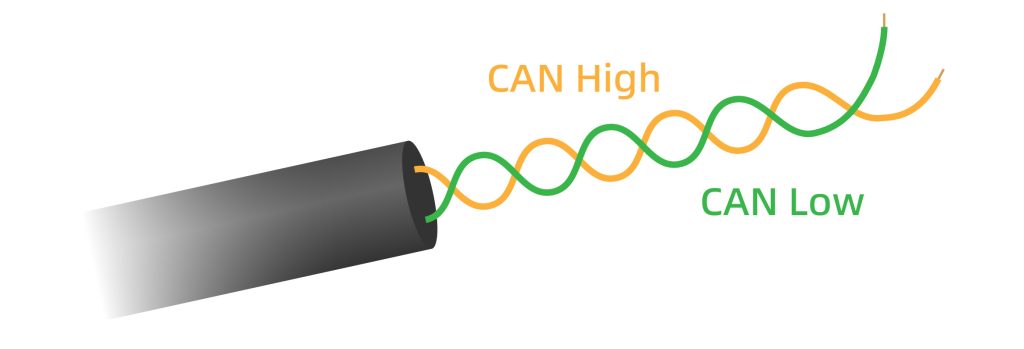
At the physical layer, a CAN network communicates over a dedicated twisted pair of wires known as CAN_H (CAN High) and CAN_L (CAN Low). The two conductors are tightly twisted to minimize electromagnetic interference and maintain stable differential signal transmission. In most wiring standards, CAN_H is color-coded yellow, and CAN_L is color-coded green for easy identification.
Differential Signaling
CAN transmits data using differential signaling generated from the voltage difference between CAN_H and CAN_L.
- When sending a dominant bit (logic 0), the CAN transceiver actively drives the bus, raising CAN_H to approximately 3.5 V and lowering CAN_L to about 1.5 V, creating a differential voltage of around 2 V.
- When sending a recessive bit (logic 1), the transceiver releases the bus, allowing both lines to return to a common reference level of about 2.5 V, resulting in a near-zero differential voltage.
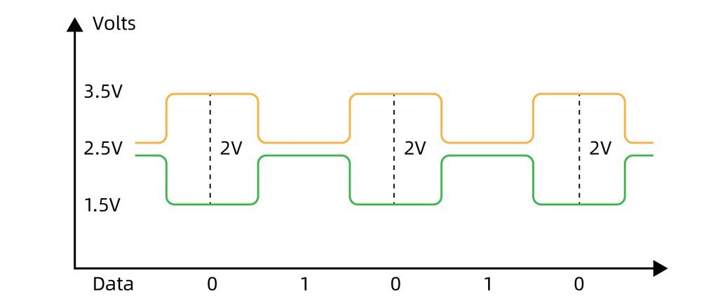
Because external noise typically affects both wires in the same way, the differential voltage remains largely unchanged, allowing the CAN bus to maintain stable communication even in electrically noisy environments.
CAN Nodes
All CAN nodes are connected in parallel to a single twisted-pair backbone consisting of CAN_H and CAN_L, forming a classic bus topology. Every device on this trunk is a CAN node. Theoretically, a CAN bus can support up to about 110 nodes. However, in real-world applications, the usable node count is often lower due to factors such as baud rate, cable length, and the electrical environment.
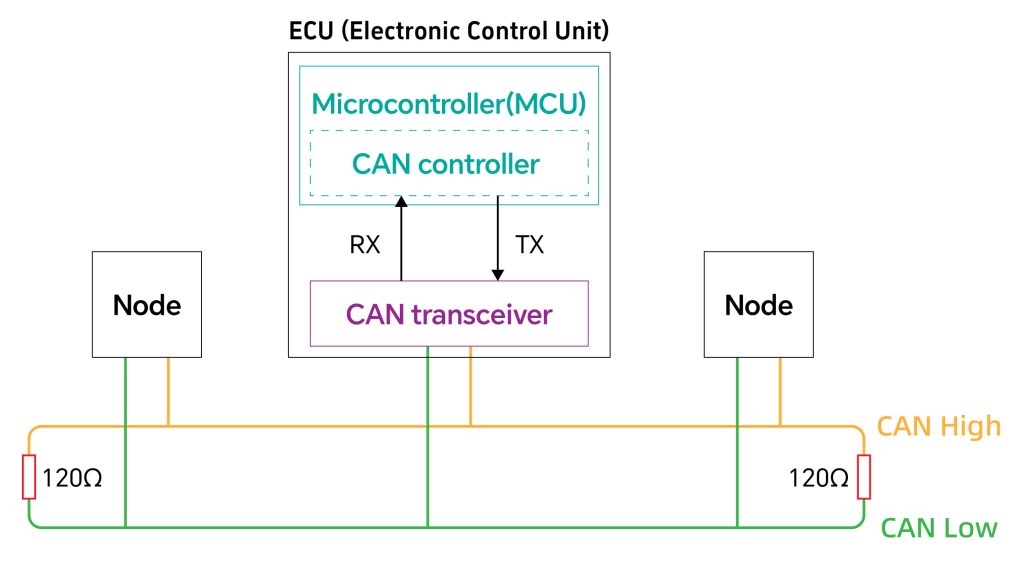
A typical node device includes the following components:
- Microcontroller: Runs the ECU’s logic. It processes incoming CAN messages and decides what data the ECU should send, such as reporting a sensor value at set intervals.
- CAN Controller: Handles the details of the CAN protocol. It formats frames, manages arbitration, filters messages, and handles errors, typically integrated within the MCU.
- CAN Transceiver: Connects the ECU to the physical bus. It converts digital signals to the differential voltages on CAN_H and CAN_L, and turns received bus signals back into digital data.
The CAN controller and CAN transceiver communicate internally through RX and TX signals. The CAN transceiver converts digital data into differential voltages and drives them onto the bus. Through the CAN_H and CAN_L lines, each ECU connects to and exchanges data with the entire CAN network.
Termination Resistors
Both ends of the CAN bus backbone require 120 Ω termination resistors. These resistors match the characteristic impedance of the twisted-pair cable and stabilize the differential signal. Without proper termination, signal reflections and noise can distort the waveform and lead to communication errors.
Understanding CAN from the OSI Model Perspective
Within the Open Systems Interconnection (OSI) model, the Controller Area Network (CAN) protocol primarily operates at the Physical Layer and the Data Link Layer. Higher-layer protocols (like CANopen or SAE J1939) build upon this foundation to define application-specific rules.
Physical Layer (ISO 11898-2)
This layer specifies the hardware requirements for communication. It defines the electrical characteristics, connectors, cabling (the CAN_H and CAN_L twisted pair), signal levels (differential voltage), bit timing, and encoding. In essence, it governs how bits are transmitted as electrical signals over the physical medium.
Data Link Layer (ISO 11898-1)
This is the core of the CAN protocol. It is often subdivided into two sub-layers:
- Logical Link Control (LLC): Handles message filtering, overload notification, and recovery management.
- Medium Access Control (MAC): Responsible for frame formatting, arbitration, error detection, signaling, and acknowledgment. The famous non-destructive bit-wise arbitration mechanism operates here.
In a practical CAN node, the CAN transceiver is a Physical Layer component, while the CAN controller implements the Data Link Layer functions. The Microcontroller Unit (MCU) runs the application software, processes received CAN messages, and determines what data to send, which belongs to higher layers.
Part 3: How CAN Bus Works: The Arbitration and Communication Process
The core operational principle of a CAN bus can be summarized as “multi-master broadcasting with priority-based arbitration.”
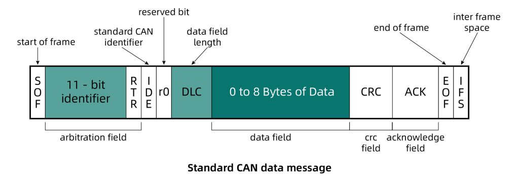
Message Frames and the Identifier (ID)
Data on a CAN bus is transmitted in structured packets called “frames.” The most important type is the Data Frame. A key part of every frame is its unique Identifier (ID). The ID serves two critical purposes:
- Defines the Message Content: Receiving nodes use the ID to decide whether to process the message.
- Determines Message Priority: A lower numerical ID value indicates a higher priority. For example, a brake signal will have a much lower ID than a window control signal, ensuring critical messages are delivered first.
Non-Destructive Bit-Wise Arbitration
This is the ingenious mechanism that enables multiple nodes to share the bus without collisions.
- When two or more nodes start transmitting a frame simultaneously, they begin by synchronously sending the bits of their Identifier field.
- Each node transmits while simultaneously listening to the state of the bus.
- If a node sends a recessive bit (logical 1) but detects a dominant bit (logical 0) on the bus, it immediately recognizes that another node is transmitting a higher-priority message.
- This node automatically stops transmitting and switches to receive mode, waiting for the bus to become free before retrying.
- Consequently, the message with the smallest identifier (highest priority) wins the arbitration without any data loss or delay and continues its transmission uninterrupted.
Data Transmission and Robust Error Handling
- The node that wins arbitration proceeds to send the rest of the frame (Control Field, Data Field, etc.). The data field is limited to a maximum of 8 bytes in Classic CAN, which ensures low latency.
- Each frame includes a Cyclic Redundancy Check (CRC) field. Receiving nodes calculate the CRC and compare it to the received value.
- If a receiving node correctly receives the frame up to the CRC field, it sends a dominant bit in the Acknowledgment (ACK) Field to confirm.
- CAN features powerful error detection mechanisms for bit errors, stuff errors, form errors, and CRC errors. Any node detecting an error immediately transmits an Error Frame, flagging the issue for the entire network. The original transmitting node then automatically retransmits the frame.
- Each node maintains error counters. A node that accumulates excessive errors will enter a “Bus Off” state, effectively disconnecting itself from the network to prevent it from disrupting overall communication.
CAN Bus Variants: CAN Bus Types Explained
High-Speed CAN
High-speed CAN was created for powertrain and safety systems that require fast, deterministic messaging. Operating up to one megabit per second under ISO 11898-2, it offers strong noise immunity and low latency, forming the backbone of modern automotive networks.
Low-Speed / Fault-Tolerant CAN
Low-speed CAN was introduced for body electronics where robustness matters more than speed. It supports up to one hundred twenty-five kilobits per second and can continue operating even with a broken wire, making it ideal for windows, mirrors, and door modules.
CAN 2.0A / CAN 2.0B
Classic CAN defines eleven-bit and twenty-nine-bit identifier formats with a fixed eight-byte payload. It enabled predictable timing, simple implementation, and broad compatibility, becoming the long-standing communication basis for automotive and industrial embedded systems.
CAN FD
CAN FD was developed to overcome Classic CAN’s bandwidth limits. By expanding payloads to sixty-four bytes and increasing the data-phase bit rate, it significantly boosts throughput, supporting modern ECUs, diagnostics, and over-the-air update needs.
CANopen
CANopen adds an application layer to CAN for industrial automation. It standardizes object dictionaries, device profiles, and network management, ensuring consistent behavior across sensors, drives, and controllers in factory environments.
CANopen FD
CANopen FD builds on CANopen by adopting CAN FD’s extended data field and higher throughput, enabling faster process data transfer and more flexible PDO mapping. It maintains CANopen’s familiar object dictionary structure while improving efficiency for modern automation and motion-control systems.
J1939
J1939 was designed for heavy-duty vehicles requiring structured, supplier-independent communication. Using extended identifiers and defined parameter groups, it provides reliable data sharing in trucks, agricultural machinery, and construction equipment.
CAN XL
CAN XL is the next-generation extension aimed at high-bandwidth, software-defined vehicle networks. It supports much larger frames and higher bit rates while retaining CAN’s deterministic arbitration, bridging the gap between CAN FD and automotive Ethernet.
Brief Comparison of CAN Bus Types
| Protocol | OSI Layers | Typical Speed | Key Features | Origin / Organization |
| High-Speed CAN (ISO 11898-2) | Physical, Data Link | Up to 1 Mbps | Low latency, strong noise immunity, core backbone for powertrain and safety systems | Bosch, ISO |
| Low-Speed / Fault-Tolerant CAN (ISO 11898-3) | Physical, Data Link | Up to 125 kbps | Fault-tolerant wiring, used in body electronics | Bosch, ISO |
| CAN 2.0A / 2.0B (Classic CAN) | Physical, Data Link | Up to 1 Mbps | 8-byte payload, 11-bit and 29-bit IDs, widespread automotive and industrial use | Bosch |
| CAN FD (ISO 11898-1:2015) | Physical, Data Link | Several Mbps in data phase | 64-byte payload, higher throughput for modern ECUs and OTA updates | Bosch, ISO |
| CANopen | Physical, Data Link, Application | Up to 1 Mbps | Industrial application layer, object dictionary, standardized device profiles | CiA |
| CANopen FD | Physical, Data Link, Application | Higher data-phase speed via CAN FD | CAN FD payloads, faster PDO transfer, efficient for automation and motion control | CiA |
| J1939 | Physical, Data Link, Application | 250 kbps typical, up to 500 kbps | Heavy-duty vehicle network, PGNs, 29-bit identifiers | SAE |
| CAN XL | Physical, Data Link | Tens of Mbps (target) | Large frames, high bandwidth with deterministic arbitration, for software-defined vehicles | Bosch, CiA, OEMs |
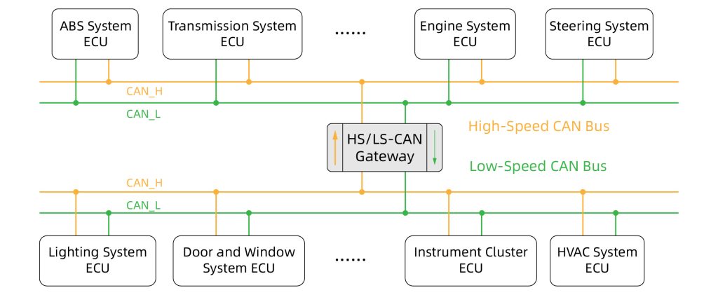
Can These CAN Bus Types Coexist?
Yes. Different CAN bus types can coexist within the same vehicle architecture. A modern car may use high-speed CAN for the engine and ABS systems, low-speed CAN for body modules, and CAN FD for ADAS units. These networks operate independently, and a CAN gateway bridges them by routing messages, translating formats, and enforcing security across domains.
Key Features of CAN Bus
Low Speed
Even the fastest CAN FD operates at lower speeds compared with other high-bandwidth networks, such as Ethernet, but CAN provides predictable timing and strong reliability for real-time control.
Long Communication Distance
Longer communication distances can be reliably supported by reducing the data rate, enabling network spans of over a kilometer.
Bit Rate Limited by Distance
The maximum achievable data rate is inversely proportional to the bus length, with 1 Mbps feasible up to ~40 meters and 125 kbps usable beyond 500 meters.
![]()
For longer links, CAN repeaters can extend the communication distance, or using CAN gateways to bridge CAN networks to Ethernet to achieve higher overall throughput and reach remote CAN segments.
Support for Many Nodes
CAN supports a large number of nodes due to its broadcast architecture and non-destructive arbitration, simplifying network expansion.
Multi-Master Capability
Every node can initiate communication and send messages without requiring a central controller, ensuring a robust and flexible network.
Priority Arbitration
Lower message identifiers transmit first, enabling deterministic, time-critical data delivery without delay for higher-priority signals.
High Reliability
Differential signaling provides robust noise immunity, making it suitable for stable operation in electrically harsh environments like vehicles.
Low Cost and Simple Wiring
Two-wire cabling significantly reduces installation cost, weight, and complexity compared to traditional point-to-point wiring harnesses.
CAN Bus Applications
CAN is widely used wherever stable, real-time control is required. Its primary domain is automotive, but many other industries rely on it for its robustness and simple wiring.
Automotive Systems
High-speed CAN links powertrain units such as engines, transmissions, and battery modules. Chassis systems like ABS, traction control, and steering sensors exchange vehicle-dynamics data. Body functions including lighting, door modules, HVAC, seats, and instrument clusters use lower-speed CAN networks.
Industrial Automation
Machines and production lines use CAN-based protocols such as CANopen to coordinate sensors, drives, and actuators with predictable timing.
Medical Equipment
Imaging devices, patient monitors, and lab instruments adopt CAN for noise-resistant, dependable internal communication.
Agriculture and Off-Highway
Tractors, construction machinery, and implements use J1939 or ISOBUS networks to share control commands, diagnostics, and position data.
Other Fields
CAN also appears in robotics, elevators, building automation, and renewable energy systems.
In these applications, CAN functions as the system’s communication backbone, carrying the control and feedback signals that keep equipment synchronized.
How to Connect a CAN Bus
Connecting a CAN bus correctly is essential for achieving stable, noise-resilient communication. The following sections outline the key considerations for connectors, topology, wiring rules, shielding, and termination.
CAN Connector Types
CAN networks can use several physical connector styles depending on the industry:
- DB9 connectors (CiA 303-1 standard): Common in industrial automation and motion control. Provides defined pinouts for CAN_H, CAN_L, CAN_GND, and shield.
- M12 connectors (A-coded or D-coded): Used in harsh industrial environments for vibration resistance and IP-rated protection.
- OBD-II connectors: Standard in automotive diagnostics, providing access to CAN networks in passenger vehicles.
- RJ45: Used in some proprietary or simplified industrial systems, though not defined by CiA standards.
- Screw Terminals / Phoenix Connectors: The most universal option. They allow direct wiring of CAN_H, CAN_L, and CAN_GND without needing adapter cables, reducing cost and compatibility issues.
In short, While dedicated CAN connectors exist, terminal blocks (screw terminals) remain the most flexible and widely compatible choice, avoiding unnecessary adapter purchases.
CAN Topology
The main backbone of a CAN Bus should ideally be a single linear bus, with all nodes connected in parallel. However, with appropriate devices such as CAN gateways or repeaters, additional branches or extended topologies can be supported at specific nodes.
Key points:
- The trunk must remain a continuous line from one end to the other.
- Only short stubs (drop lines) should branch from the backbone; long stubs cause reflections.
- Maximum recommended stub length is typically < 30 cm, depending on bit rate.
CAN Wiring Rules
Proper wiring is critical for reliable CAN communication. Industry-recommended guidelines include:
Twisted Pair Requirement
CAN_H and CAN_L must be twisted together to preserve differential signal balance. Typical requirement: at least 40 twists per meter (or 20 twists per foot).
Stub Length
Keep stubs as short as possible (ideally under 30 cm) to avoid signal reflections.
Wire Gauge
Use shielded twisted-pair cable with appropriate gauge:
Common: 22–24 AWG for most automotive and industrial systems.
Distance and Bit Rate
Higher bit rates require shorter cable lengths.
Shielding, Grounding, and Termination
Shielding
Use high-quality shielded CAN cable to minimize EMI.
- Shield must be grounded at both ends (multi-point grounding) for maximum noise suppression.
- Connect shield either to the system’s protective earth, inverter chassis, or a designated ENC_GND pin.
- All stubs must maintain shielding continuity.
Grounding (CAN GND)
Devices must share a common reference ground.
- The CAN_GND conductor must run in the same shielded cable as CAN_H and CAN_L.
- If a device lacks a dedicated CAN_GND pin, connect to the device’s main ground.
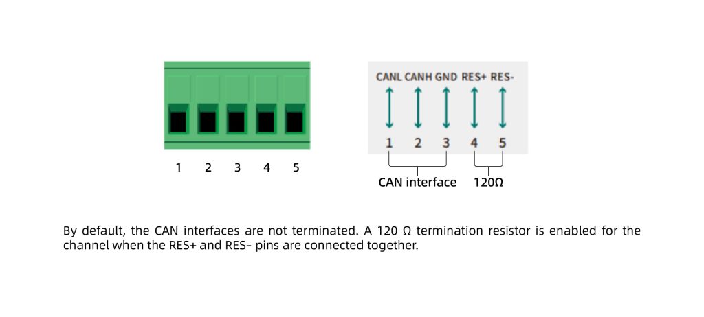
Termination
The bus requires two 120-ohm resistors, one at each end of the trunk.
- Combined resistance between CAN_H and CAN_L should measure ≈ 60 ohms.
- Improper termination leads to reflections, noise, and unstable communication.
Clearance from High-Voltage Cables
To reduce EMI exposure:
- Maintain at least 30 cm distance from power cables, inverters, or any high-voltage wiring.
CAN Bus Gateway: Integrate CAN to Your Network Seamlessly
While CAN (Controller Area Network) is widely used for real-time communication in automotive and industrial systems, it has inherent limitations. High-speed CAN networks are limited in transmission distance, so devices located far apart may experience communication issues. Even with CAN FD, network speed is still relatively low compared with Ethernet, and longer cables reduce achievable bit rates.
Modern systems often involve multiple CAN variants, such as Classic CAN, CAN FD, and CANopen, as well as other network types like Ethernet, Modbus, or serial interfaces. Integrating these diverse protocols across different devices presents a significant challenge. Engineers need a solution to extend coverage, bridge networks, and convert protocols seamlessly without redesigning the entire system.
Come-Star CAN solutions address these challenges effectively:
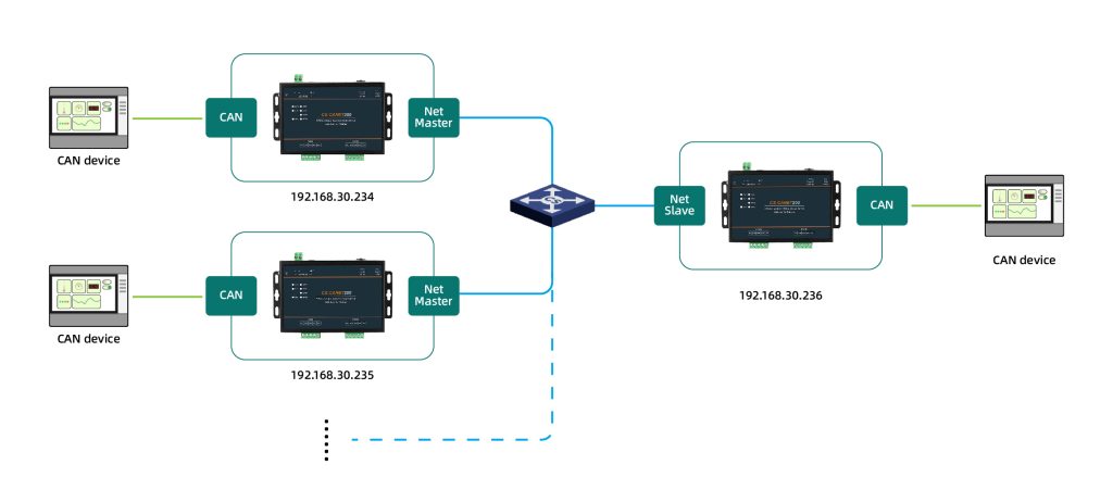
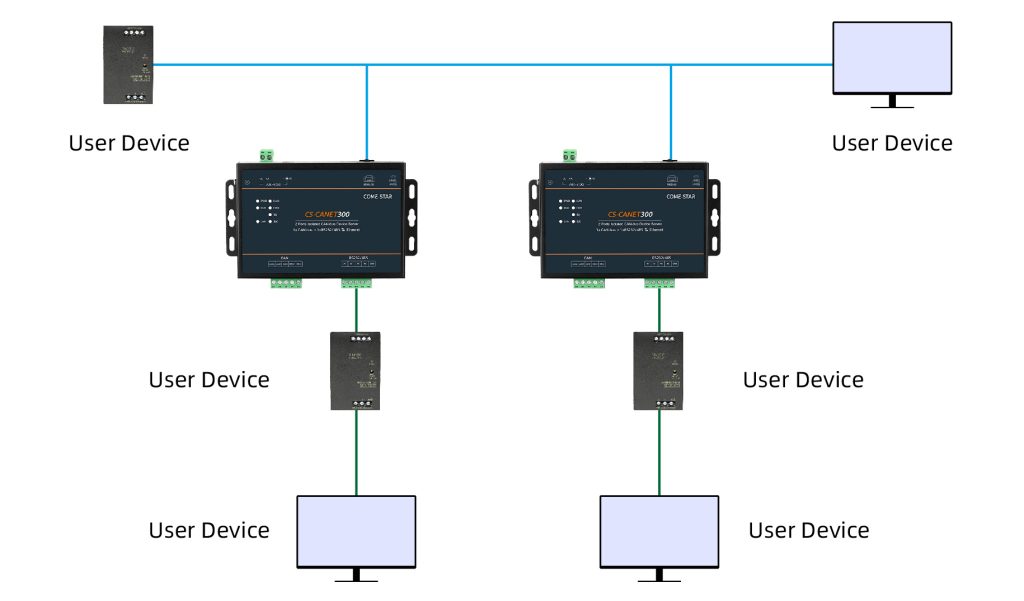
- Extend Network Range with CAN Repeater Capability – Built-in CAN repeater functionality allows signals to travel longer distances while maintaining data integrity, overcoming the speed-distance trade-off inherent in CAN networks.
![]()
- Bridge Remote CAN Networks – Using gateways with CAN translator functionality, different CAN segments can communicate across large areas or via Ethernet, ensuring consistent, low-latency data exchange.
- Integrate with Other Systems Using CAN Adaptor Features – CAN data can be seamlessly converted to Ethernet, Modbus, or serial networks, enabling legacy devices and modern controllers to interoperate without manual protocol handling.
- Flexible Network Topologies at Nodes – With appropriate devices such as CAN gateways or repeaters, individual nodes can support extended topologies like star or tree structures, allowing greater design flexibility while keeping the main CAN backbone linear.
By deploying these solutions, engineers can simplify network architectures, support multiple CAN variants in a single system, and maintain reliable real-time communication across all nodes.
Performance and Industrial Advantages of Come-Star CAN Converters
Come-Star converters are designed for demanding environments:
- Flexible Interfaces – Terminal block connections allow direct wiring of CAN_H/CAN_L, avoiding proprietary connectors and reducing deployment cost.
- Configurable Termination – Adjustable 120 Ω resistors ensure signal stability across various topologies.
- Independent CAN Ports – Each port can operate at its own baud rate, supporting multiple network segments simultaneously.
- Industrial-Grade Reliability – Operating from –40 °C to +85 °C with strong EMC protection, these devices maintain stable communication even in harsh automotive or factory conditions.
With these capabilities, Come-Star CAN solutions provide a scalable, reliable, and flexible communication infrastructure, solving real-world CAN network challenges.
Conclusion
CAN Bus is a robust, real-time communication protocol designed for demanding industrial and automotive applications. Its differential signaling, priority-based arbitration, and multi-master architecture make it ideal for high-speed, safety-critical, and noise-prone environments.
When combined with CAN gateways or protocol converters, such as those from Come-Star, CAN networks can seamlessly integrate with other protocols like Modbus or Ethernet, extend communication range, and support multiple network topologies. Come-Star solutions ensure industrial-grade reliability, flexible deployment, and simplified system integration, enabling engineers to build scalable, high-performance networks that meet modern control and automation requirements. Welcome to visit our blog to learn more about CAN Bus and industrial communication, or contact us directly for the products and solutions you need.