In industrial communication systems, compatibility and coordination between different protocols have always been important issues in system design. Among them, the topic of “CAN bus vs Modbus” has long been frequently discussed by engineers during system selection and integration. CAN bus and Modbus are widely used in industrial automation and embedded control fields. However, due to differences in communication mechanisms, data organization methods, and network structures, they are often difficult to interconnect directly in practical systems.Therefore, understanding the difference between CAN bus and Modbus is essential for system design and integration.
In many industrial application scenarios, lower-level devices typically use CAN bus for high-speed and real-time data communication, while upper-level control systems or monitoring platforms mostly use the Modbus protocol for data acquisition and management. Although this layered architecture allows each system to operate efficiently, it also brings a practical issue: when CAN and Modbus coexist in the same system, how can data be connected and shared between the two communication methods?
What are CAN and Modbus
Modbus
Modbus is an application-layer protocol developed in 1979 by Modicon for PLC control systems. It adopts a master-slave architecture (Client-Server model). Its core feature is simplicity and ease of implementation, enabling data exchange between devices through function codes (such as 03 Read Holding Registers and 06 Write Single Register). Modbus supports multiple physical interfaces, including RS-485/RS-232 serial communication and Modbus TCP over Ethernet, and is widely used in industrial automation and data acquisition systems.
CAN
CAN (Controller Area Network) was developed by Bosch in 1983 for automotive electronics and belongs to the data link layer protocol. It adopts a multi-master architecture (peer-to-peer communication) and uses 11-bit or 29-bit identifiers for non-destructive arbitration. At the hardware level, CAN has strong error detection capabilities (CRC + error frames) and priority arbitration mechanisms, making it perform excellently in scenarios requiring high real-time performance, such as automotive CAN bus systems controlling engines and transmissions.
Related Article: Understanding Modbus and CAN Bus: Features, Pros & Cons, and Conversion Solutions
CAN vs Modbus: Key Differences
Communication Type
Modbus uses a master-slave communication structure, where the master device initiates requests and slave devices respond with data. In contrast, CAN supports multi-master communication, where any node can actively transmit data when the bus is idle.
Protocol Layer and Network Topology
Modbus is mainly an application-layer protocol that can run on serial or Ethernet physical interfaces. Its network topology is typically bus or star, depending on the physical connection. CAN, on the other hand, is a data link layer protocol that usually adopts a bus topology, although branch structures are allowed.
Communication Rate and Real-Time Performance
Modbus supports a maximum communication rate of 115.2 kbps over serial connections and up to 100 Mbps in its Ethernet version. However, its real-time performance depends on polling cycles and is relatively slower. In contrast, CAN communication speed is closely related to transmission distance and typically ranges from 10 kbps to 1 Mbps, offering higher real-time performance.
Addressing Method and Frame Structure
Modbus uses a unique address for each slave device and follows a request-response frame structure. CAN nodes are identified by message identifiers (ID), and message priority is determined by the ID. Frame structures include data frames, remote frames, error frames, and overload frames.
Error Detection
Both Modbus and CAN use CRC checks to ensure data integrity. Additionally, CAN supports bit stuffing and acknowledgment mechanisms to enhance communication reliability.
Data Length and Hardware Interface
Modbus typically reads and writes 1 to 125 registers per transaction and supports RS-232/RS-485 or TCP/IP interfaces. CAN frame data length is 8 bytes in classic CAN and can be extended to 64 bytes in CAN FD, requiring dedicated CAN transceivers.
Application Scenarios
Modbus is widely used in industrial automation, instrumentation, and data acquisition systems. CAN is mainly used in automotive electronics, industrial control networks, and sensor networks, especially in scenarios requiring high real-time performance.
| Difference Between CAN bus and Modbus | ||
| Comparison Item | Modbus | CAN (CAN Bus) |
| Communication Type | Master-slave communication, initiated by master | Multi-master communication, any node can transmit |
| Protocol Layer & Topology | Application layer, runs on RS-232/RS-485 or Ethernet, bus or star topology | Data link layer, typically bus topology |
| Communication Rate & Real-Time | Up to 115.2 kbps (serial), 100 Mbps (Ethernet), lower real-time performance | 10 kbps–1 Mbps (distance-related), high real-time performance |
| Addressing & Frame | Slave address-based, request-response structure | ID-based, priority arbitration, multiple frame types |
| Error Detection | CRC check | CRC + bit stuffing + error frames + acknowledgment |
| Data Length & Interface | 1–125 registers, serial and TCP/IP | 8 bytes/frame (64 bytes for CAN FD), requires CAN transceiver |
| Application | Industrial automation, instrumentation, data acquisition | Automotive, industrial control, sensor networks |
Although there are significant differences between Modbus and CAN in communication mechanisms and protocol layers, these two technologies often coexist in the same network environment in real industrial systems. Therefore, a common question arises: under such architectural differences, how can data interoperability between Modbus and CAN be achieved?
How to Connect Modbus to CAN
In practical engineering, if data exchange between Modbus devices and CAN networks is required, a protocol conversion mechanism must be introduced.
The common approach is to use a Modbus to CAN gateway (protocol converter). This device is also commonly referred to as a CAN bus to Modbus converter.
This device acts as a “bridge” in the system, connecting to the Modbus network (such as RS-485 or Modbus TCP) on one side and the CAN bus on the other side. Its core functions include:
- Parsing Modbus requests and mapping them to CAN messages
- Converting CAN data into Modbus register data according to rules
- Providing data buffering and scheduling between the two communication mechanisms
A reliable CAN to Modbus converter ensures stable communication between the two systems.
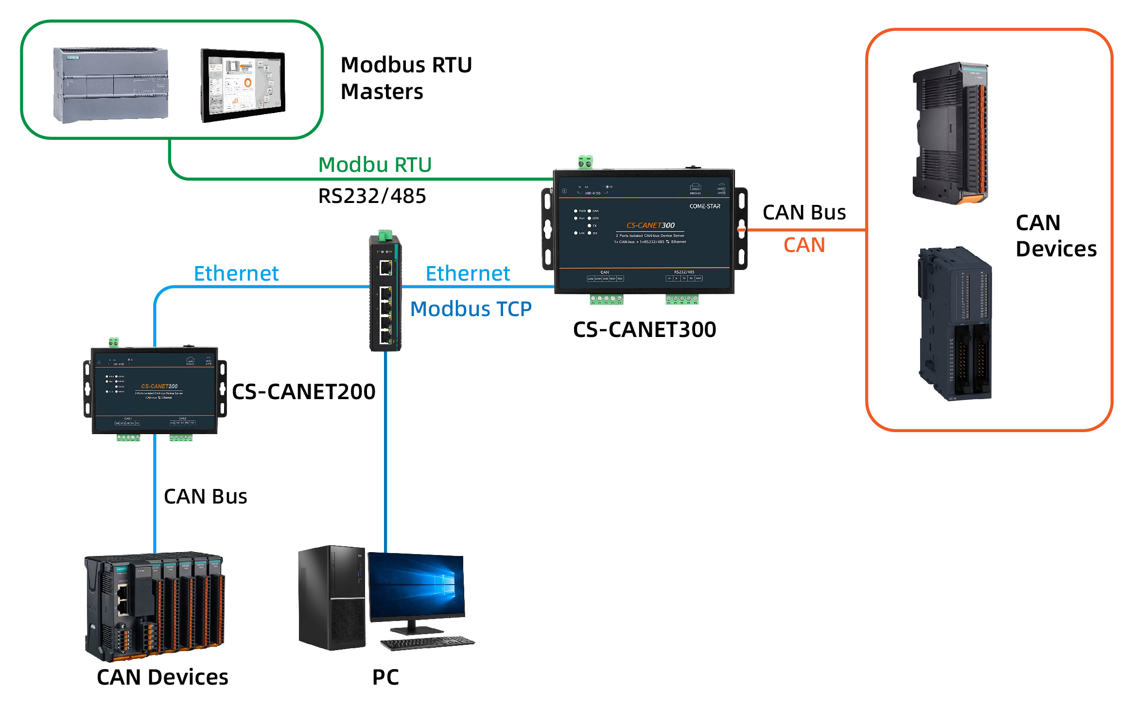
Come-Star provides two types of CAN and Modbus conversion solutions to meet this requirement, suitable for different system architectures and communication methods.
- CS-CANET200 is a CAN to Ethernet device that connects CAN data to a network and converts it into Modbus TCP, enabling communication with host computers or industrial Ethernet systems. It also supports CAN relay functionality, ensuring transparent data transmission in complex network environments and enabling stable and efficient interconnection between CAN and Modbus networks.
- CS-CANET300 supports both Ethernet and serial interfaces, enabling conversion from CAN to Modbus TCP and Modbus RTU. It can communicate with host systems via Ethernet or connect to traditional serial devices through RS232/485. It also supports multiple modes, including transparent transmission, transparent transmission with identifier, format conversion, and Modbus conversion, making it suitable for multi-protocol integration and complex application scenarios.
FAQ
Q1: What methods are supported for CAN to Modbus conversion?
Typically, Modbus RTU and Modbus TCP are supported, corresponding to serial communication and Ethernet communication scenarios.
Q2: Are CAN bus to Modbus converters compatible with all CAN bus devices?
Compatibility depends on support for CAN protocol versions and frame types. Come-Star CAN to Modbus converters support common standards such as CAN 2.0A and 2.0B.
Q3: How to choose a suitable CAN to Modbus converter?
Consider support for Modbus RTU/TCP, CAN interface compatibility, and data mapping capabilities. Also choose the appropriate interface (serial or Ethernet) based on your application, and ensure good anti-interference performance for stable communication.
Conclusion
In summary, although CAN bus and Modbus have significant differences in protocol layers and communication mechanisms, they often need to work together within the same network architecture in real industrial systems. Therefore, achieving stable communication between CAN and Modbus is not only a common requirement in system integration but also an important step in improving overall device connectivity.
By introducing an appropriate CAN to Modbus gateway, communication barriers between different protocols can be effectively eliminated. In Ethernet-based architectures, CAN can be converted to Modbus TCP, while in serial systems, interoperability between CAN and Modbus RTU devices can be achieved.
By selecting the appropriate conversion solution based on actual application requirements, system compatibility can be achieved without changing the original device architecture, while significantly improving the flexibility and scalability of data communication. This approach is widely applicable in industrial automation, device networking, and remote monitoring scenarios.